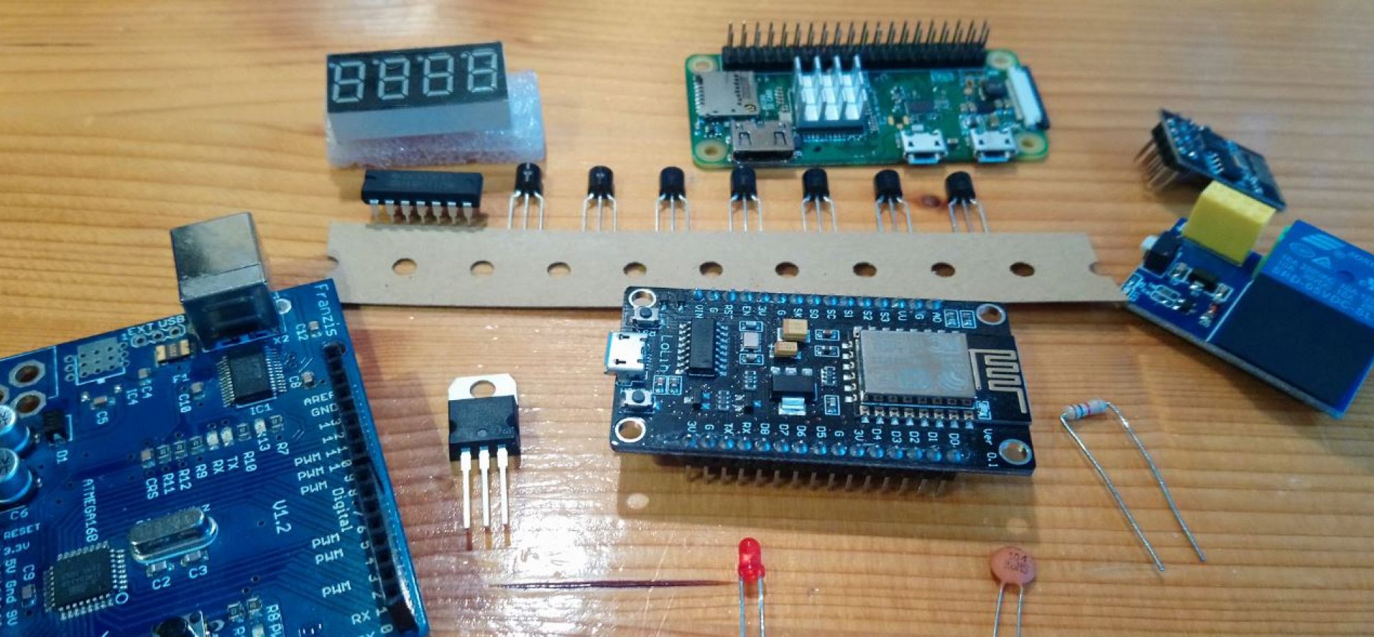
Did you ever woke up in the morning wishing to have your first coffee already brewed? Well, this project may be you solution! For this automation project we simply need a coffe machine, one 230V AC to 5V DC converter and a relay in combination with an ESP-01, have a look at the linkes below:
Caution: In this project we deal with 230 Volts! This requires prior knowledge and should only be done by persons with appropriate training and experience. The author will not take responsibility for any damage caused by the use of information provided below.
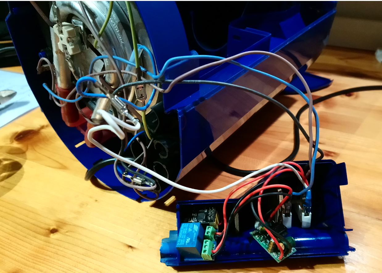
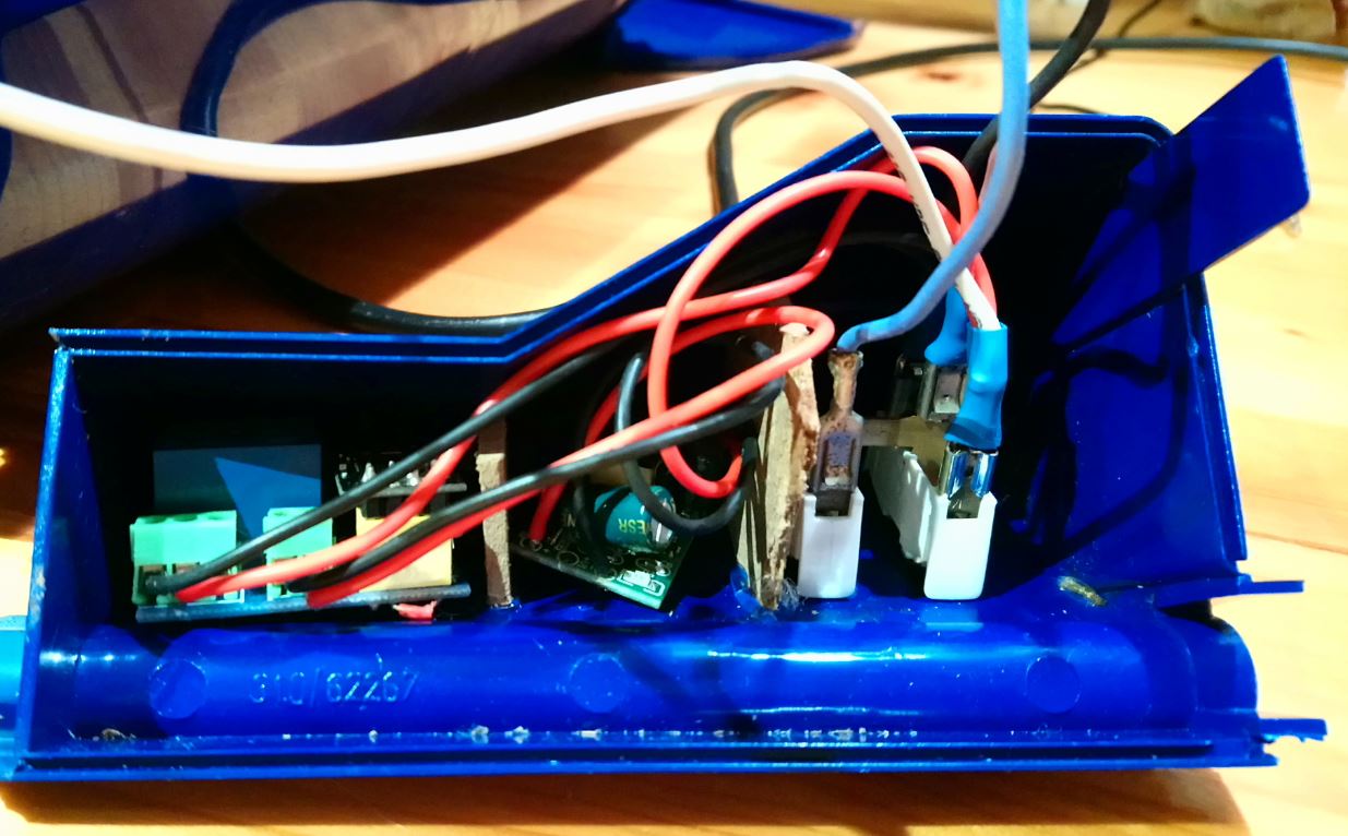
For the first step disassemble the coffe machine until you have access to the connections of the power switch. Near by you need to find some space in the housing where the relay and the power converter can be placed. Make sure that the position has no contact to water, steam or heat! In the second step connect the the relay parallel to the switch using the NO (normally opened) connector. Then connect the relay board with the 5 Volt output of the converter. For the input find a place where you can attach it to 230 Volts. Commonly the power switch has a light to indicate wether it is turned on or off. There it probably is possible to contact with the 230 Volts. Make sure that every connection is perfectly isolated – safety first! I added some small seperating walls between the converter, relay and the power switch to realy make sure they do not come in contact with each other. See the pictures below.
Once everything is connected program the ESP-01. You may use this code:
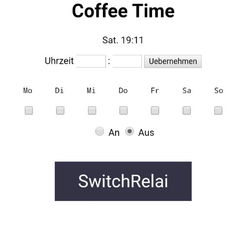
It contains a webserver where you can program date and time to switch on the relay. Besides it includes a NTP client to get the time. You just need to add your Wifi SSID and password in Wifi.cpp.
Double check all connections, plug the ESP into the relay board and connect the coffee machine to mains. Try to switch your coffe machine on and off via the webserver running on the ESP. Once everything works fine reassemble all parts of the coffee machine, prepare it to brew some coffee, program the desired time, wait and enjoy your coffee!
By using Arduino tone() function in combination with a small piezo element it is easy to produce some tones and sounds. Once single tone frequencies are known you can make some musik.
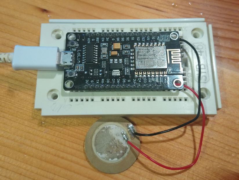
In this small project I used a NodeMCU ESP8266 to program the beginning of Super Marios soundtrack. Just Connect the piezo element to ground and D1 and it will work. Make sure that the element is not in touch with other objects since this will lead to some inconvinient noises. The tone functions receives a pin, frequency and duration parameter. Code can be downloaded here have fun!
Within this project I started my first self made aquarium automation with the goal to build a timer for light control and two pumps for automated plant fertilization. The whole electrical system based on a Raspberry Pi 0 W is mounted in a wooden box and fits perfectly into the base cabinet of my fish tank (Juwel Rio 240L). This article will start with a basic overview of what I have done so far before going into detail describing every single part. Lets get started!
Caution: In this project we deal with 230 Volts! This requires prior knowledge and should only be done by persons with appropriate training and experience. The author will not take responsibility for any damage caused by the use of information provided below.
Overview
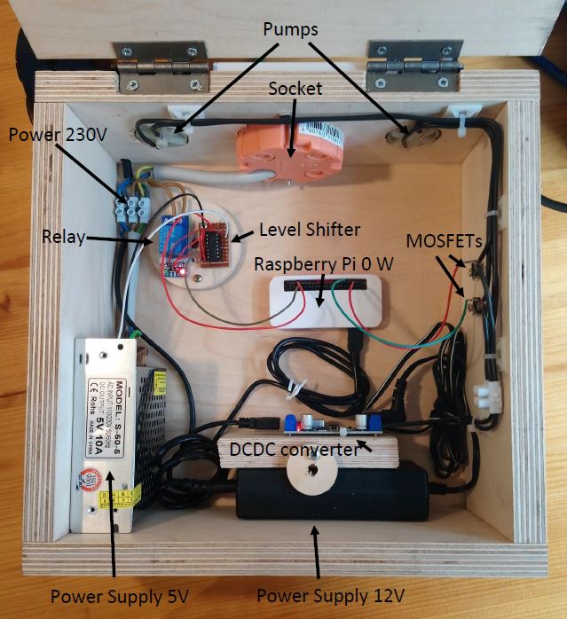
The picture below shows the box made from birch plywood (multiplex) and its interior. At the upper left corner we can see the mains power connection coming inside. It is connected to two power supplies providing 12 and 5 Volts. The current configuration is mainly powerd by the 12 Volt power supply, since the other one is implemented to power some RGB LEDs in the future. However, a relay and a level shifter are already connected to the 5 Volt output. A 12 Volt source is required to drive the two peristaltic pumps, which are responsible for the fertilizer going into the aquarium. It is also connected to a 5 Volts DCDC converter which powers the Raspberry Pi. This may sound confusing since there is a 5 Volts power supply which could to the job also, but it is pretty convenient to work with this DCDC converter becaus of its USB output connector which can directly be connected to the Pi. Another advantage are the clamps at the 5 and 12 Volts side with which the conntection to the pumps can easily be established. The „heart“ of the box is the Raspberry Pi 0 W. It can connect both pumps separatly to 12 Volts using two MOSFETs which are mounted on the right hand side. For the light control a level shifter is required in order to drive the 5 Volts input at the relay with an 3.3 Volts output from the Raspberry. The relay itself will connect the socket to mains where the power plug of the light can be attached. With a lid it is possible to close the box which hides all the cables and provides some protection from outer influences.
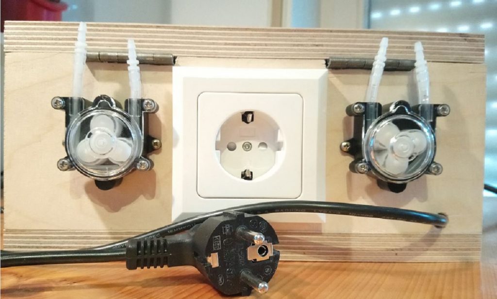
On the next picture a backside view of the box is given.
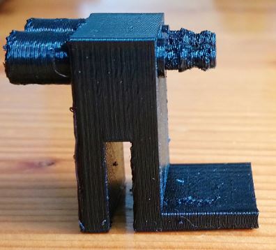
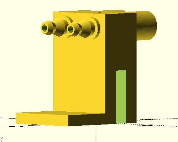
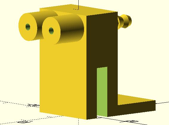
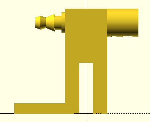
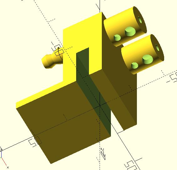
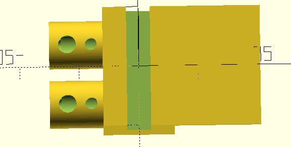
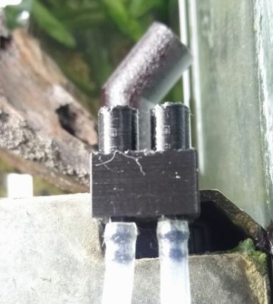
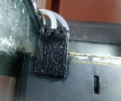
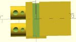
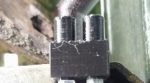
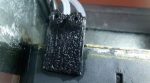
Two five liter canister of fertilizer, namely Aquarebell Makro Basic NPK and Aqua Rebell Mikro Basic Eisenvolldünger, will be connected to the pumps with some silicone hoses. From there it is pumped into the aquarium using silicone hoses as well. In order to have a fixed attachment to the aquarium I made a 3D-print using PETG which can be connected to the internal filter of my aquarium. The result is shown in the next figure. On the right hand side you can see the input and the connectors of the hoses. Left hand side is the output where the fertilizer gets into the aquarium. A slot in the middle is used to plug it on top of the internal filter. The right angle is intended to be placed below the lid of the filter to provide some extra stability. A way to make sure that the fertilizer does not squirt at the output due to the pressure of the pumps, the 3D design and the printing configuration will be discussed in greater detail later on.
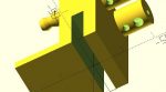
3D-Printing The 3D-print was designed in OpenSCAD which is a free of charge computer-aided design (CAD) software. It is pretty easy to use and after some time playing around with basic geometric structures you will be able to design more complex things. Within the programm you can view the current look of your desing. The follwoing pictures demonstrate how the design looks in OpenSCAD and how it is mounted at the filter.
You may have noticed three holes at the output. Their purpose is to reduce the pressure comming from the pumps to prevent squirting when the fertilizer is pumped into the aquarium. Once the design is finished you can export the data as an .stl file. Afterwards it needs to be imported into a slicing program to generate g-code which is used to control the 3D-printer. In my case I used Cura from Ultimaker which also is free of charge. When the g-code is generated you are able to start printing. Important to mention are the teperature conditions with which the design is printed. Here I printed with 60°C bed temperature and 240°C at the nozzel. In case that you want to do something similar feel free to download the code and change it to your own purposes. You can find it here!
Electrical Stuff As already mentioned everything is controled by a Raspberry Pi 0 W. In my opinion this is a pretty convenient choice when it comes to projects which don’t need lots of perfomance and you want to have access via a terminal program too. The Pi supports wireless LAN and only needs a power supply to get started. Another advantage is the small size. It receives its power via the 12 to 5 Volt DCDC converter which is connected to the 12 Volt power supply.
Light Let us consider the light control first. The Pi controls a relay with one of its GPIO pins. Between the Pi and the relay is a level shifter to rise the signal level from 3.3 to 5 Volts. This is required to drive the input of our relay. You could also use a transistor to do this but I need the level shifter to control some LED stripes in the future anyhow. The relay itself is low active, meaning whenever you connect its input to ground it will power the internal coil. It has one normaly closed (NC) and one nomaly opened (NO) connector. Hence when the input is connected to ground the NC-connector is opened and the NO-connector is closed. In this project I used the NO-connector in order to switch the light on when the Pi connects the input to ground. Here is something you need to know because the pins of the Pi are either HIGH or LOW by default. Imagine you conncte your relay to a pin which will have a LOW state by default. The result is your relay switches on right after your Pi is powered on which you probably don’t want. Instead connect it to a pin which is HIGH by default so the state of the relay does not change when the Pi gets connected to a power supply and the relay control only depends on your code. The relay connctes the socket with mains where you can plug in the power connector of your light. In my case two fluorescent tubes. Befor you start buildinfg something like that on your own please make sure that you understand how every single part is working especially at the part with 230 Volts since failures can be life threatening! The timing of the light control will be discussed in the code section.
Fertilization To get the liquid fertilizer into the aquarium two peristaltic pumps are used which are powered by the 12 Volt power supply. They need a current of 200 to 300 mA each. Two MOSFETs work as switches connecting the pumps with the power supply. The Pi uses two GPIO pins to control them separately. Via the amount of time the pumps are powered on you are able to define the volume which is pumped into the aquarium. I did some measurement and found that they pump 2 ml per second approximately. Make sure that you connect the gates of the MOSFETs to a GPIO pin which has a LOW level after booting the Pi. Otherwise the pumps directly start running without any control!
Code As you may have expected the code written in Python is pretty easy. Simply switching some GPIOs on and off. The Pi gets the actual time via the WiFi connection but you need to make sure that your code snippets are executed at the time you want them to run. For that reason I wrote two python files for the light control. One file changes the output state from HIGH to LOW hence the light is switched on and the other one does the opposite switching it off. There is no timing included only GPIO control. To execute the code at a certain time I implemented two bash files which execute the python files. Don’t forget to make them executable! These bash files are executed by crontab which is a service to execute scripts at a certain time. At some time during the morning the file which sets the GPIO pin to LOW is executed and during the evening the other file to set the pin to HIGH level is executed. With the fertilization it is a bit different. Here you need to calculate a time period the pumps need to be powered on in order to pump a cartain volume. I only wrote one python file which includes the change of the GPIO signal from LOW to HIGH and some timing until the GPIOs are turned to LOW again. The pumps run sequentially. One more bash script to execute this python code and then implement this to the crontab as well. The light control runs every day of course while the fertilizer is pumped into the aquarium two times a week.
Congrats we are done! In case that you like the project or you have any further questions leave a comment.
We use cookies on our website to give you the most relevant experience by remembering your preferences and repeat visits. By clicking “Accept”, you consent to the use of ALL the cookies.
This website uses cookies to improve your experience while you navigate through the website. Out of these, the cookies that are categorized as necessary are stored on your browser as they are essential for the working of basic functionalities of the website. We also use third-party cookies that help us analyze and understand how you use this website. These cookies will be stored in your browser only with your consent. You also have the option to opt-out of these cookies. But opting out of some of these cookies may affect your browsing experience.
Necessary cookies are absolutely essential for the website to function properly. This category only includes cookies that ensures basic functionalities and security features of the website. These cookies do not store any personal information.
Any cookies that may not be particularly necessary for the website to function and is used specifically to collect user personal data via analytics, ads, other embedded contents are termed as non-necessary cookies. It is mandatory to procure user consent prior to running these cookies on your website.